Getting The Wedge Barriers To Work
The smart Trick of Wedge Barriers That Nobody is Discussing

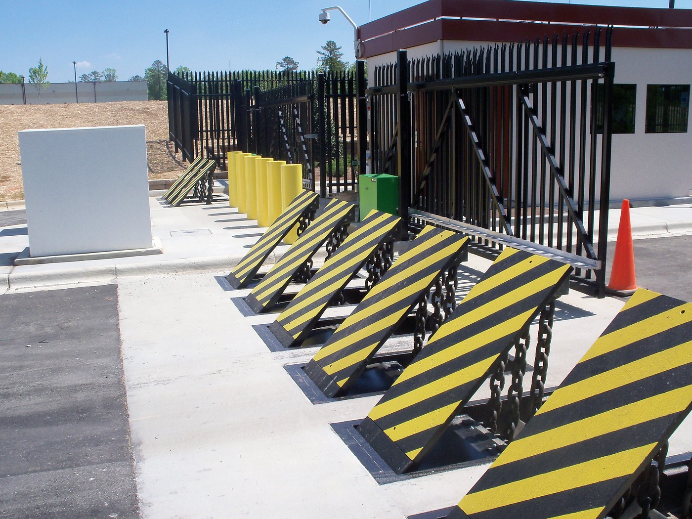
18 may be done more rapidly, quickly, and cost properly. FIG. In particular personifications, the support 30 may be a steel framework consisting of plates, beam of lights(e. g., I-beams ), and/or other structures that are protected within the foundation 14, which might be concrete. At the surface 12, a top side 28 of the anchor 30 might be at least partly revealed
, thus allowing the add-on of the obstacle 10 to the anchor 30. g., threaded holes)in one or more light beams or plates of the anchor 30 might be exposed to the surface area 12. In this fashion, screws 32 or other mechanical fasteners might be made use of to safeguard the obstacle 10 to the support 30. As the obstacle 10 is mounted to the surface 12 of the structure 14, collection of particles and various other product below the barrier might be minimized, and parts of the bather 10 may not be revealed to below grade settings. As suggested by recommendation numeral 52, the lifting device 50 includes components disposed under the wedge plate 16. The parts 52 below the wedge plate 16 might include an electromechanical actuator, a cam, one or even more web cam surface areas, and so forth. Furthermore, the lifting mechanism 50 consists of a springtime setting up 54
The spring pole 58 is coupled to a cam(e. g., camera 80 displayed in FIG. 4) of the lifting device 50. The springtimes 60 disposed about the spring rod 58 are kept in compression by spring sustains 62, including a dealt with spring assistance 64. That is, the fixed springtime support 64 is repaired loved one to the foundation 14 and the remainder of the bather 10.
The Best Strategy To Use For Wedge Barriers
The staying pressure used to
the cam to deploy the wedge plate 16 may be provided by an electromechanical actuator 84 or other various other. The springtime assembly 54 and the actuator 84(e. Wedge Barriers. g., electromechanical actuator)may operate with each other to equate the webcam and lift the wedge plate 16.
As mentioned over, the spring assembly 54 exerts a constant force on the webcam, while the electromechanical actuator might be managed to apply a variable pressure on the web cam, thereby enabling the training and reducing( i. e., deploying and pulling back )of the wedge plate 16. In certain embodiments, the constant pressure here are the findings used by the springtime setting up 54 may be flexible. g., electromechanical actuator) is impaired. As will be valued, the springtime assembly 54 may be covered and secured from debris or other components by a cover plate(e. g., cover plate 68 displayed in FIG. 4) that may be substantially flush with the raised surface area 38 of the foundation 14. As discussed over, in the released setting, the wedge plate 16 serves to obstruct gain access to or traveling past the obstacle 10. The obstacle 10(e. g., the wedge plate 16 )might obstruct pedestrians or lorries from accessing a property or path. As reviewed above, the obstacle 10 is affixed to the anchor 30 safeguarded within the structure 14,

front braces 71. Therefore, the linkage assemblies 72 might pivot and revolve to enable the collapse and expansion of the affiliation settings up 72 throughout retraction and deployment of the bather 10. The affiliation assemblies 72 reason movement of the wedge plate 16 to be limited. If a lorry is taking a trip in the direction of the deployed wedge plate 16(e. For example, in one scenario, the security legs 86 may be prolonged throughoutmaintenance of the barrier 10. When the safety legs 86 are deployed, the safety and security legs 86 sustain the weight of the wedge plate 16 versus the surface area 12. Because of this, the lifting device 50 might be shut off, serviced, removed, changed, etc. FIG. 5 is partial viewpoint sight of a personification of the surface-mounted wedge-style obstacle 10, illustrating the webcam 80 and the web cam surface areas 82 of the training device 50. Especially, 2 camera surface areas 82, which are described as reduced web cam surfaces 83, are positioned listed below the webcam 80. The reduced cam surfaces 83 might be taken care of to the surface area 12 (e. As an example, the reduced camera surfaces view website 83 and the installing plate 85 may form a solitary piece that is safeguarded to the anchor 30 by bolts or various other mechanical bolts. Additionally, two camera surface areas 82, which are described as upper web cam surface areas 87, are positioned above the web cam 80 and combined to (e. In other personifications, intervening look at this web-site layers or plates may be positioned between the surface 12 and the lower camera surface areas 83 and/or the wedge plate 16 and the top cam surface areas 87 As discussed above, the web cam
80 equates along the web cam surface areas 82 when the wedge plate 16 is lifted from the pulled back placement to the released position. Additionally, as mentioned over, the spring setting up 54 (see FIG. 3 )may supply a force acting upon the camera 80 in the direction 102 through springtime rod 58, which might minimize the pressure the electromechanical actuator 84 is needed to apply to the cam 80 in order to actuate and raise the wedge plate 16. 1 )to the deployed placement(see FIG. 4). As shown, the cam 80 includes track wheels 104(e. g., rollers), which contact and translate along the cam surfaces 82 throughout procedure.